

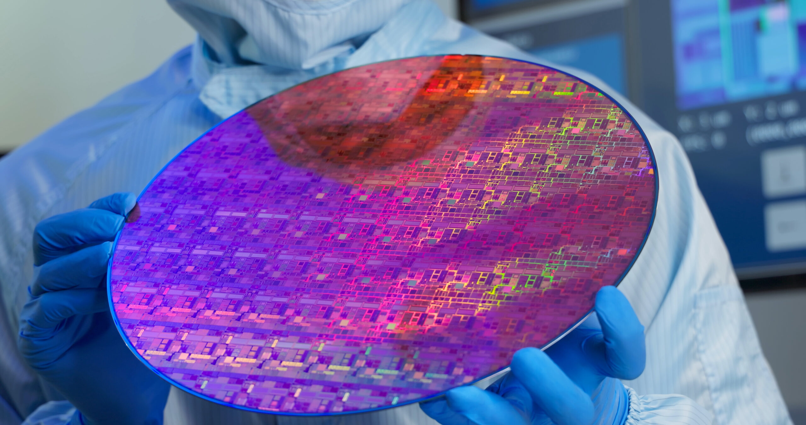
Brightfield and darkfield illumination are the foundational techniques behind many LED-based inspection systems. Together, they enable visualization of surface features, defects, and material properties in life science and industrial applications. Brightfield captures directly reflected light to reveal surface uniformity, coatings, and subtle intensity variations, while darkfield isolates scattered light to highlight defects, contamination, and surface irregularities. TechniQuip is committed to providing full, smart illumination systems, rather than a sole component, to improve contrast, detection accuracy, and inspection consistency.
Why Brightfield & Darkfield Illumination Matter in Life Science and Industrial Systems
Inspection doesn’t fail because defects aren’t there. It fails because they aren’t visible.
In semiconductor inspection, medical device manufacturing, and industrial automation, many defects are not hidden because cameras lack resolution. The real culprit is that the wrong illumination strategy is being used. A scratch that disappears under brightfield illumination may become obvious under darkfield. A coating defect invisible under darkfield may be immediately revealed under coaxial brightfield.
What if the defect isn’t actually invisible? The difference between passing and failing a part often comes down to one question: Are you illuminating the feature correctly?
Going Beyond Fixed Lighting Geometries
Modern inspection challenges require more than fixed lighting geometries. Defects do not present themselves consistently. They interact with light differently based on size, material, orientation, and environment. Capturing them requires illumination systems that can dynamically adjust and sequence multiple approaches.
Programmable illumination systems enable engineers to control:
- Angle
- Intensity
- Pulse timing
- Wavelength
- Polarization
This allows users to move beyond static inspection and create inspection sequences, combining brightfield, darkfield, and advanced techniques in a single workflow.
At TechniQuip, we believe this is the difference between delivering a component and enabling an intelligent inspection tool. Our systems are designed to help OEMs ensure quality in their samples on all fronts, not just illuminating them.
How Illumination Strategy is the Key to Quality
In modern inspection systems, illumination acts as an active interrogation of an object to reveal hidden information. But choosing the right illumination strategy is vital in getting the right results. Engineers who rely on a single lighting geometry often see only part of the story.
The most effective inspection systems treat illumination as a sequence of controlled experiments:
- Change the angle → reveal edges and topography
- Adjust intensity → isolate subtle contrast differences
- Shift wavelength → expose material-dependent features
- Switch from brightfield to darkfield → separate reflectivity from scatter
Each variation asks a different question of the sample. Together, they build a complete answer.
And this approach is utilized every day across industries to show critical defects that are simply hidden under the wrong illumination conditions.
Semiconductor Inspection
Think about a polished silicon wafer. Under coaxial brightfield illumination, where uniform reflection masks sub-micron contamination, it may appear flawless. But under darkfield illumination, those same particles scatter light and immediately become visible as bright points against a dark background.
This is why advanced wafer inspection systems rarely rely on a single method. They combine multiple illumination geometries to detect both subtle film variations and discrete contamination events.
Medical Device Inspection
Semiconductor inspection is not the only industry that uses this approach. Looking at medical devices, imagine a catheter ready for inspection. Under standard illumination, the coating appears uniform.
However, brightfield imaging would reveal coating thickness variations and surface inconsistencies. And if you implement darkfield illumination, particulate contamination would be visible (which directly impacts patient safety and regulatory compliance).
In this context, illumination is directly tied to risk detection, not just visualization.
Choosing the Right Brightfield Illumination Technique
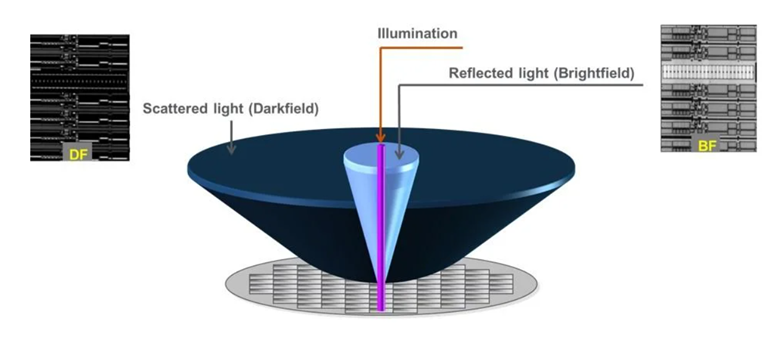
Brightfield illumination directs light towards an object’s surface and captures the specular and near-specular reflected components. Image contrast is primarily generated by local variations in reflectivity, absorption, and geometry, making it a reflectance-based imaging method. Defects or features appear as small perturbations in intensity rather than strong contrast discontinuities. This makes brightfield especially suited for detecting subtle variations rather than discrete particles.
This technique is critical in both industrial and life science inspection systems for assessing pattern integrity, coating consistency, surface tone, and material uniformity.
Coaxial Brightfield (CBF)
Coaxial brightfield illumination delivers light perpendicular to the surface with a half-mirror or beam splitter that directs the light down, directly to the surface. The reflected light returns up along the same optical path as the camera. Contrast imaging is driven by differences in reflectivity and pattern geometry, making this approach highly effective for uniform, mirror-like surfaces. It serves as the foundation for many inspection tasks, especially when detecting subtle intensity variations across flat regions.
This technique has several advantages, including: high signal-to-noise ratio (SNR) on reflective surfaces, repeatable contrast due to controlled optical path, and minimal sensitivity to orientation or feature directionality.
Key Applications & Use Cases:
- Pattern review and continuity assessment
- Detection of surface tone changes on polished materials
- Inspection of coatings and thin films
- Life science surface treatment verification, such as catheters, microfluidic chips, glass slides, etc.
- General defect capture on smooth surfaces
Key surface features that indicate the need for CBF:
- Low-contrast, grey-on-grey patterns
- Defects appearing as slight bright or dark patches
- Subtle coating inconsistencies or surface treatment variations
Oblique/Multi-Azimuth Brightfield (OBF/MABF)
Oblique and multi-azimuth brightfield illumination introduce light from multiple directional angles. With oblique illumination, the light sources are at a low, slanted angle to create intentional shadowing. On the other hand, multi-azimuth illumination uses multiple lighting sources from multiple directions (or azimuths) to reduce blind spots by capturing from varying angles.
As light direction changes, shadows and highlights shift, revealing features that are otherwise invisible under direct illumination. This directional sensitivity makes OBF/MABF especially powerful for identifying edges, surface discontinuities, and shallow topography.
Key Applications & Use Cases:
- Scratches and surface damage detection
- Edge and sidewall feature visibility
- Identification of laser grooving marks
- Detection of chips and shallow surface variations
Key surface features that indicate the need for OBF/MABF:
- Defects that flip from bright to dark as illumination direction changes
- Strong edge contrast driven by directional lighting
When to Use Darkfield Illumination
Darkfield illumination is the direct foil of brightfield illumination. It rejects specular reflection and focuses on isolating scattered light components. Instead of measuring reflected intensity, it captures light redistributed by surface irregularities or micro particles.
This technique is vital to defect detection and contamination control in both life science and industrial applications. In these applications, darkfield illumination is often used to detect particles, micro-scratches, surface contaminations, fibers, residues, polishing defects, etc.
Darkfield Scatter Inspection (DF)
Darkfield illumination blocks specular (direct) reflection and instead captures only scattered light from surface irregularities, minimizing background signal. Smooth surfaces appear dark, while particles, defects, and roughness scatter light and become highly visible. This technique is extremely sensitive to small contaminants and micro-scale defects, making it especially valuable in controlled life science and industrial inspection environments where cleanliness is critical.
Key Applications & Use Cases:
- Particle and contamination detection
- Micro-scratch identification, especially in wafer inspection
- Detection of small protrusions or surface roughness
- Inspection for bioburden or residue on biomedical components
Key surface features that indicate the need for DF:
- Bright specks, threads, or “sparkle” against a dark background
- High contrast between defects and surrounding surface
- Trace contaminants or residues that may not be visible under direct illumination
TechniQuip’s Talon™ illumination platform is often used for darkfield scatter inspection in semiconductor inspection. Read about it now.
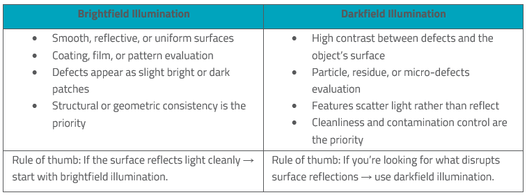
Choosing between brightfield and darkfield depends on the type of features you need to detect and how those features interact with light:
Advanced LED Illumination Methods Beyond Brightfield & Darkfield
Polarization Illumination (POL)
Polarized illumination controls the orientation of light wave oscillations during both illumination and analysis. This enables contrast mechanisms based on anisotropy, stress, and polarization-dependent reflectance, revealing information beyond simple brightness differences.
Key Applications & Use Cases:
- Stress signature analysis in glass and polymers
- Detection of cracks and structural inconsistencies
- Material and texture differentiation
- Inspection where intensity contrast alone is insufficient
Key surface features that indicate the need for POL:
- Features that appear or disappear as polarization is adjusted
- Contrast shifts tied to material properties rather than geometry
Spectral Illumination (UV – IR)
Spectral illumination uses specific wavelengths as tuning variables to change both contrast and depth sensitivity. By shifting from ultraviolet (UV) to infrared (IR), paired with advanced sensors, it highlights chemical properties, physical defects, or tissue structures that direct illumination cannot pick up.
Key Applications & Use Cases:
- UV: Detection of organic residues, surface haze, and thin film variations
- IR: Visualization of subsurface features, internal cracks, and deeper structures
- Inspection of coatings, bonded layers, and complex materials
Key surface features that indicate the need for spectral illumination:
- UV: Surface haze or contaminants become highly visible
- IR: Soft outlines of subsurface features and internal structures emerge
3D/Interferometric (3D/INT)
3D and interferometric techniques use coherent or structured light to generate fringe patterns or phase signals. This enables precise measurement of surface height and topography. Unlike intensity-based methods, these approaches merge LED illumination with interferometry to provide quantitative dimensional measurements while reducing laser speckle noise in high-precision surface characterization.
Key Applications & Use Cases:
- Surface planarity and warpage measurement
- Micro-feature and bump metrology
- Height and depth characterization of small structures
- Precision placement and alignment verification
Key surface features that indicate the need for 3D/INT:
- Fringe patterns indicating surface variation
- Quantitative height maps revealing topography
What You Don’t See Is What Costs You
Inspection performance is often limited not by the camera, sensor, or software, but by illumination.
The right illumination strategy determines whether a defect becomes visible, a process remains in control, and critical quality issues are caught before reaching the customer. If your current system relies on fixed lighting, there is a high likelihood that you are missing critical information.
Both brightfield and darkfield illumination offer a distinct way to interact with a surface, whether it be highlighting reflectivity differences, revealing edges, isolating particles, or exposing subsurface structures. And sometimes, they often work together to capture every aspect of an object.
At TechniQuip, we help OEMs design illumination architectures that reveal what conventional lighting misses. Because the goal isn’t simply to see. It’s to see what matters.
Partner with TechiQuip’s team of experts today to select the right illumination system for your application.